<?xml version="1.0" encoding="utf-8"?><feed xmlns="http://www.w3.org/2005/Atom" ><generator uri="https://jekyllrb.com/" version="4.4.1">Jekyll</generator><link href="https://ryan.fish/feed.xml" rel="self" type="application/atom+xml" /><link href="https://ryan.fish/" rel="alternate" type="text/html" /><updated>2026-07-30T10:29:37-04:00</updated><id>https://ryan.fish/feed.xml</id><title type="html">The Caffeinated Fish</title><subtitle>Engineering, robotics and photography from a forester&apos;s son. Like a caffeinated fish, it&apos;s high signal in an otherwise noisy environment. © 2026 Ryan Fish, All Rights Reserved.</subtitle><author><name>Ryan Fish</name></author><entry><title type="html">Integrating a Staubli TX2-40 with ROS - Architecture</title><link href="https://ryan.fish/projects/2024/10/25/staubli-ros-node.html" rel="alternate" type="text/html" title="Integrating a Staubli TX2-40 with ROS - Architecture" /><published>2024-10-25T15:34:22-04:00</published><updated>2024-10-25T15:34:22-04:00</updated><id>https://ryan.fish/projects/2024/10/25/staubli-ros-node</id><content type="html" xml:base="https://ryan.fish/projects/2024/10/25/staubli-ros-node.html"><![CDATA[<p>Incredibly, I was able to purchase a very lightly used Staubli robotic arm and its controller for (relatively) cheap! The Staubli TX2-40 is their smallest offering, it’s payload is only a few kg, but it does have the best dynamics of their offerings (makes sense, it’s light). Not especially known for being spry, I’ve been curious about how to maximize the dynamic reponse of these arms in task space. To start with, I’d like to do some simple impedance control of the end-effector.</p>

<p>While the controller itself is incredibly basic, the bulk of the work will be integrating the arm into ROS (which I want for future extensibility). Setting up a driver node and the connection from that ROS node to the driver “firmware” running on the Staubli controller will be an interesting task.</p>

<p>The Staubli CS9 controller uses it’s own language to give integrators access to hardware registers, control modes, set destinations, and interact with the GUI on the user “pendant” for guided applications. The language, called VAL3, is vaguely C-like but without any indirection, and logical blocks sort of like Basic. It’s a little nerfed, I think to avoid programming errors that are a little more dangerous in this context than just on a computer. But very functional at the small overhead of more functions and variables than “optimal”.</p>

<p>There is <a href="https://wiki.ros.org/staubli">an existing ROS integration for Staubli</a> robotic arms, but it is very basic, exposing only point-to-point motion capabilities and relying on Staubli’s controller for all path-planning and lower-level performance. This is a nice abstraction for pick-and-place applications, but defeats my eventual goals for force control at the end-effector.  Trajectories often take upwards of 200ms to clear even for sub-millimeter motions, since the controller has to plan, execute and verify the trajectory.</p>

<p>Instead, I’m going to take advantage of one of the advanced features in the controller (free for evaluation if you’re ok restarting the controller every once in a while), a function called <code class="language-plaintext highlighter-rouge">alter</code>. Originally designed for sanding/buffing/polishing applications, it allows applying an offset to the current trajectory. This allows “injecting” feedback into the controller from other sources, where otherwise it would operate rigidly on its own encoders and that’s it. The key twist is that the trajectory for the controller is not deemed complete until <code class="language-plaintext highlighter-rouge">alter</code> mode is exited. In this way, we can start a trajectory with a tiny epsilon and immediately enter <code class="language-plaintext highlighter-rouge">alter</code> mode, and from there control our position directly from ROS until we wish to exit. We can perform our own analysis of termination criteria, run our trajectory control live, and incorporate whatever sensing we want into the final control effort output. Perfect!</p>]]></content><author><name>Ryan Fish</name></author><category term="projects" /><summary type="html"><![CDATA[Incredibly, I was able to purchase a very lightly used Staubli robotic arm and its controller for (relatively) cheap! The Staubli TX2-40 is their smallest offering, it’s payload is only a few kg, but it does have the best dynamics of their offerings (makes sense, it’s light). Not especially known for being spry, I’ve been curious about how to maximize the dynamic reponse of these arms in task space. To start with, I’d like to do some simple impedance control of the end-effector.]]></summary></entry><entry><title type="html">Using Make to Encode the Date and Time in BCD</title><link href="https://ryan.fish/other/2016/08/24/using-make-to-encode-the-date-and-time-in-bcd.html" rel="alternate" type="text/html" title="Using Make to Encode the Date and Time in BCD" /><published>2016-08-24T09:50:11-04:00</published><updated>2016-08-24T09:50:11-04:00</updated><id>https://ryan.fish/other/2016/08/24/using-make-to-encode-the-date-and-time-in-bcd</id><content type="html" xml:base="https://ryan.fish/other/2016/08/24/using-make-to-encode-the-date-and-time-in-bcd.html"><![CDATA[<p>I tried pretty hard several times over the past day to find a pre-built solution for doing this.  This, being, program the “current” (to a few seconds) date and time into my STM32F4’s RTC for initialization, using a couple <a href="https://en.wikipedia.org/wiki/Binary-coded_decimal" target="_blank">BCD</a> words.  Unable to find it (seriously? Does everyone program it from a user interface?  I doubt that…), I had to create my own solution.  My build tools being generally <code>bash</code> and <code>make</code>, I figured it should simply be a matter of setting <code>date</code> to the right output type.  People make BCD clocks all the time, right?</p>

<p><code>date</code> is a wonderful utility, but doesn’t have a BCD output (and probably shouldn’t since there are a million different ways to order the digits), so I just needed to process its output.  Fine, this is fine.  Giving <code>date</code> the argument +%-H,%-M,%-S tells it to output something like 20,12,43 to say the time is 20:12:43.  My friend <code>awk</code> can be given custom field delimiters through the -F flag (but for silly reasons some characters are better than others, I choose commas since they are generally safe), and generate a string as output.  Unfortunately, the printf command in <code>awk</code> doesn’t have a way to print things as binary (hex and dec are fine).  Sooooo, next utility at bat is <code>bc</code>, essentially a command line calculator with some nicer features than most unix command line builtins.  Critically, it can convert numbers between arbitrary bases.</p>

<p>At this point, the general scheme is to have <code>make</code> do a shell call and grab the output.  The shell call will be a call to <code>date</code> piped into <code>awk</code> which will build the command string to be piped to <code>bc</code> which will do the math and binary conversion necessary to get a set of decimal hours, minutes and seconds converted to a 32bit integer that matches the encoding for the STM32F446 (and potentially other chips in the STM32F4 line).</p>

<p>The final relevant <code>make</code> lines are as follows:</p>

<p><code>
RTC_BCD_TIME := 0b$(shell  date +%-H,%-M,%-S | awk -F"," '{print "obase=2;scale=0;hours="$$1";minutes="$$2";seconds="$$3";(((hours/10)*1048576)+((hours%10)*65536)+((minutes/10)*4096)+((minutes%10)*256)+((seconds/10)*16)+(seconds%10))"}' - | bc )
RTC_BCD_DATE := 0b$(shell  date +%-y,%-m,%-d,%-w | awk -F"," '{print "obase=2;scale=0;years="$$1";months="$$2";days="$$3";dayofweek="$$4";if(dayofweek==0)dayofweek=7;(((years/10)*1048576)+((years%10)*65536)+((months/10)*4096)+((months%10)*256)+(dayofweek*8192)+((days/10)*16)+(days%10))"}' - | bc)
</code></p>

<p>Note prepending the string returned by the shell call with “0b” to designate it as a binary sequence.  I guess at the end of the day it didn’t need to be converted to binary, but it may help with debugging later on since it is BCD.  It’s also worthwhile to be aware of the <strong>DATE</strong> and <strong>TIME</strong> automatically defined by gcc, but they are in string form and difficult to manipulate with just define statements.  I felt like doing this outside the compiler was a better option.  If anyone finds themselves in the same scenario, hope this helps!</p>]]></content><author><name>Ryan Fish</name></author><category term="other" /><summary type="html"><![CDATA[I tried pretty hard several times over the past day to find a pre-built solution for doing this. This, being, program the “current” (to a few seconds) date and time into my STM32F4’s RTC for initialization, using a couple BCD words. Unable to find it (seriously? Does everyone program it from a user interface? I doubt that…), I had to create my own solution. My build tools being generally bash and make, I figured it should simply be a matter of setting date to the right output type. People make BCD clocks all the time, right?]]></summary></entry><entry><title type="html">Tee and Moira 2 (or, the Better Option)</title><link href="https://ryan.fish/other/2016/08/23/tee-and-moira-2-or-the-better-option.html" rel="alternate" type="text/html" title="Tee and Moira 2 (or, the Better Option)" /><published>2016-08-23T07:32:43-04:00</published><updated>2016-08-23T07:32:43-04:00</updated><id>https://ryan.fish/other/2016/08/23/tee-and-moira-2-or-the-better-option</id><content type="html" xml:base="https://ryan.fish/other/2016/08/23/tee-and-moira-2-or-the-better-option.html"><![CDATA[<p>So, <a href="/other/2016/08/22/tee-and-moira.html">last time</a> I had found the <code>moira</code> interactive prompt utility which had a habit of just ultra-dumping my moira-list membership list along with a ton of control characters and excess prompt word schmoo.  This is undesirable because any attempt to make a find-and-replace style moira list utility would require major cleanup of the logged output from the interactive prompt.  However, since anything worth over-doing was once worth just plain doing, I knew there had to be a more naked utility hiding under the overall moira prompt.</p>

<p>Queue the MIT SIPB site, particularly its page <a href="https://sipb.mit.edu/doc/moira/" target="_blank">on moira</a> (<em>doh!</em>)  Scroll to the bottom, you find “Making Moira Queries Directly,” and the acronym GLOM, get_lists_of_member.  Perform a query (qy), of type glom (glom) to recursively find all memberships of a user (ruser) with the username (NAME) is the magic (mostly) answer!</p>

<p><code>qy glom ruser NAME</code></p>

<p>I say mostly because in this raw form it also releases a bunch of other information, but at least in an entirely repeatable (read, removable) fashion.  However, more digging on the SIPB site shows that <code>qy _help glom</code> can give us more info on the glom-type query, its data-fields (importantly, list_name), and how to tell <code>qy</code> we only want the list_name field.</p>

<p>Appending <code>-f list_name</code> is the ticket, (again, mostly) to filter out the other data we don’t want.  There is still “list_name:” prepended to everything, but at least a convenient colon is there to delimit.</p>

<p>Apparently, (typing as I’m working on this), <code>-s</code> is the final key!  Add that and each list name is set nicely on its own line, without any fluff.  Perfect!</p>

<p>For the next trick, a forum post tipped my off that <code>awk</code> is a useful utility for iterating through newline-delimited input.  Typically, <code>awk '/searchstring/ {print $0;}' inputfile</code> is a silly way to <code>grep</code>-style search through <code>inputfile</code> and print any lines matching the regex <code>searchstring</code>.  <code>$0</code> is the “field” of the input line that matched <code>searchstring</code> for which you can craft the delimiters for.  Luckily, I’ve already cleaned up the input so each line is a single string that is the only thing of interest, so everything here on out will use <code>$0</code>.</p>

<p><code>awk</code> is also designed to use input files, and must be given “<code>-</code>” as the input file to be told to use stdin (e.g. to use piped input).  so <code>CMD | awk '/foo/ {print $0;}' -</code> gets use well on our way.</p>

<p>Printing is very useful for debugging, but we want to actually do things at this point.  The command sent to awk in the curly braces isn’t automatically a shell command; awk is an interpreter and has its own command set.  Luckily it is easy to just pipe a print command through to shell: <code>CMD | awk '/foo/ {print $0 | "/bin/sh"}' -</code>  will run whatever the matching lines are (which probably won’t be very useful).</p>

<p>Padding the print statement with some actual commands is the final step:</p>

<p><code>qy glom user NAME -f list_name -s | awk '{print "blanche "$0" -a LISTNAME" | "/bin/sh"}' -</code></p>

<p>This pipes the list of base moira lists of which NAME is a member, omits the optional filter in awk (processes all input), pipes the blanche command to a shell with the current line’s list as the first arg, then the -a option with LISTNAME as the moira member to add to the list.</p>

<p>Essentially, run this replacing NAME for your kerberos, and replacing LISTNAME for a moira list or member, to add LISTNAME to all lists you have permissions to modify and NAME is a member of.  Obviously, you may not have permissions for every list you are a member of, but awk will print these errors and failover to the next line.  Neat!</p>]]></content><author><name>Ryan Fish</name></author><category term="other" /><summary type="html"><![CDATA[So, last time I had found the moira interactive prompt utility which had a habit of just ultra-dumping my moira-list membership list along with a ton of control characters and excess prompt word schmoo. This is undesirable because any attempt to make a find-and-replace style moira list utility would require major cleanup of the logged output from the interactive prompt. However, since anything worth over-doing was once worth just plain doing, I knew there had to be a more naked utility hiding under the overall moira prompt.]]></summary></entry><entry><title type="html">Tee and Moira</title><link href="https://ryan.fish/other/2016/08/22/tee-and-moira.html" rel="alternate" type="text/html" title="Tee and Moira" /><published>2016-08-22T09:23:00-04:00</published><updated>2016-08-22T09:23:00-04:00</updated><id>https://ryan.fish/other/2016/08/22/tee-and-moira</id><content type="html" xml:base="https://ryan.fish/other/2016/08/22/tee-and-moira.html"><![CDATA[<p>So, as all aging MIT students must, today I set about looking into adding my future email address to the mailing lists I’d like to remain on post-graduation.  Obviously, it would be desirable to do so programatically rather than clicking through the <a href="http://web.mit.edu/moira" target="_blank">Web Moira</a> interface for the 700 lists I’m on and manually adding my new email to each.  First things first, I know about and have used Blanche to add myself to lists and get info about lists.  However, blanche doesn’t allow you to search by kerberos and get a list of memberships.  The Googles allowed me to find <a href="http://ist.mit.edu/software/athena/utilities" target="_blank">a list of Athena utilities</a> (including Blanche if you’re curious) that includes the Moira command-line interface!</p>

<p>It’s really a silly little interactive prompt that assumes you know way more about how things work than you probably do, but gets the job done in a somewhat unsatisfactory way.  I’ll keep looking for options or a better utility.  My work thus far:</p>

<p>1). Get yo’self an Athena dialup session or log in in a cluster  <em>gasp!</em>
2). Pull up a terminal and enter <code>moira</code>
3). Option 3 for the <code>Lists and Group Menu</code>
4). Option 7 for the <code>List Info Menu</code>
5). Option 1 for the <code>Show all lists to which a given member belongs</code>
6). If you haven’t done anything crazy with how you logged in (you’ll know already if you are) the defaults should give you everything you ever wanted (just hit enter at each remaining prompt, it will autofill USER and your kerb name)
7). The output is a less-formatted spew of all the lists you are on!</p>

<p>This is great but I’m hardly going to copy paste this.  It’s annoying that the output is embedded in an interactive prompt.  I suppose a funny way to do it could be to run this inside <code>screen</code>, modify the apparent window height, then take advantage of the scrollback buffer and Copy Mode to scroll back to the start of output and copy all the lists to the screen buffer.  But that’s gross.</p>

<p>So far, my target is still gross.  Enter <code>tee</code> which allows the interception of the usual stdin/out/err descriptors, with particular utility for logging them to files.  Running:</p>

<p><code>moira | tee moira.txt</code></p>

<p>logs the output for the entire interactive session!  Unfortunately, they used vt100 or similar terminal coding to blank the display, reset to home, and write the next prompt instead of whitespacing out the old stuff (for the record though, that’s 100% how you should do it, its just frustrating for the log files) so the logs are full of ESC[ gobbledeegook.  oops.  soooooo, automated cleanup, or a more better programmatic way of things?  Next time!</p>]]></content><author><name>Ryan Fish</name></author><category term="other" /><summary type="html"><![CDATA[So, as all aging MIT students must, today I set about looking into adding my future email address to the mailing lists I’d like to remain on post-graduation. Obviously, it would be desirable to do so programatically rather than clicking through the Web Moira interface for the 700 lists I’m on and manually adding my new email to each. First things first, I know about and have used Blanche to add myself to lists and get info about lists. However, blanche doesn’t allow you to search by kerberos and get a list of memberships. The Googles allowed me to find a list of Athena utilities (including Blanche if you’re curious) that includes the Moira command-line interface!]]></summary></entry><entry><title type="html">Triangulating Camera Position from Known Points</title><link href="https://ryan.fish/projects/2016/08/02/triangulating-camera-position-from-known-points.html" rel="alternate" type="text/html" title="Triangulating Camera Position from Known Points" /><published>2016-08-02T10:42:37-04:00</published><updated>2016-08-02T10:42:37-04:00</updated><id>https://ryan.fish/projects/2016/08/02/triangulating-camera-position-from-known-points</id><content type="html" xml:base="https://ryan.fish/projects/2016/08/02/triangulating-camera-position-from-known-points.html"><![CDATA[<figure>
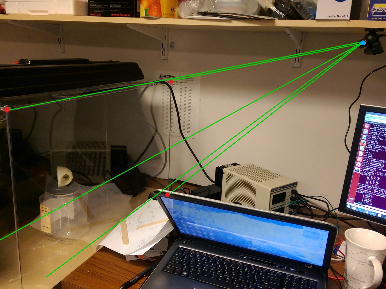
  <img src="/images/camera_triangulation1.jpg" alt="" width="75%" />
  
    <figcaption>Triangulating camera position from known points with OpenCV</figcaption>
  
</figure>

<p>As per my last post on this effort, <a href="/projects/2016/08/02/characterizing-the-ps3-eye.html">characterizing the ps3 eye</a>, with the camera field of view parameters determined, and the lensing warp shown to be fairly low, there’s a straightforward path to taking an array of 2D points in the camera view, with known real-world coordinates, and backprojecting them to determine the camera’s position in space.  Though this has probably been done a million times before by every vision system ever, it seemed like the kind of thing that should be easy!  Or, as is often the case, would turn out to be interesting on its own and therefore worth the experience.  :D</p>

<p>Given my ultimate goal of extracting my swimming robot’s coordinates from a dual-camera setup, I need to know both cameras’ poses in the global reference frame to make a sensible coordinate extraction.  So, with a static fishtank in the frame, containing the robot as well as generating perfect markers for a rectangular coordinate frame, I set about doing lots of trig.  Essentially, the corners of the fishtank become a set of points in <a href="https://en.wikipedia.org/wiki/Three-dimensional_space_(mathematics)" target="_blank">ℝ<sup>3</sup></a>, with known coordinates since I can measure the fishtank.  It’s a perfect rectangular prism, so it makes sense to align the global coordinate frame with its axes.  Given 4 points on the fishtank, I can triangulate the camera location (and likely orientation though I haven’t thought that through yet and don’t need it).</p>

<p>Basic Method:</p>

<p>In OpenCV, click my 4 registration points on the 2D camera feed.</p>

<p>Given the pixel distance -&gt; angle conversion I talked about in the previous post on the subject, convert every combination of 2 points to an angular measure.</p>

<p>Since the actual 3D position of all the points is known, the distance between any set of 2 is also known.</p>

<p>Taking each pair and considering the “point” location of the camera, it is clear there is a triangle for every point pair with the camera location as its third point.</p>

<p>The known distance between the two points on the fishtank is then opposite the angle determined by the pixel distance of the point pairs.</p>

<p>This should sound exactly like its heading towards the <a href="https://en.wikipedia.org/wiki/Law_of_cosines" target="_blank">Law of Cosines</a> to determine the other sides of a triangle with one angle known.</p>

<p>Since all of these imaginary triangles actually share sides with each other, a simple algebraic relationship exists to find all side lengths of all triangles from the known sides and the angles (these side lengths can also be interpreted as the distance from fishtank points to camera point).</p>

<p>To get back to what we actually want, the camera position in 3D, we can replace side lengths as values with side lengths as a function of the camera position.  Instead of getting the lengths of every side, we do a little more algebra and get back from the solver the point that satisfies the distances.</p>

<p>If the world were perfect, we could stop there and call it a day.  Just take the angles from the camera and the known line lengths from the fishtank points, run it through solver and boom, a point in ℝ<sup>3</sup>.  If we were working with exact values, this could happen, but a lot of approximations have happened thus far (the actual dimensions of the fishtank, the selected points from the video feed, the assumption of a perfect pixel to angle conversion, among others).</p>

<p>So instead we are left with having to find the camera point that minimizes the error between the computer world and the real world.  We can start from a test point in space, check how badly it fits our equations by comparing the triangles it makes with the edge lengths and angles we know, then try new points that make this error smaller.  Its essentially a “hot or cold” search where you drag a point through space, getting constant feedback of “hotter” or “colder”.</p>

<p>Fortunately, this works great!</p>

<p>Some notes on this:</p>

<p>I first did a demo in MATLAB, since the visualization tools there are a little easier to use.  There I discovered a few flaws, the biggest being that only optimizing for the point is globally stable, optimizing the distances of the camera to each point has some local minima that can trap the solver.</p>

<p>The second is that a non-linear optimizer like <code>fmincon</code> in MATLAB is really a math-package’s bread and butter, and they are not letting anyone peek under the hood.  <code>fmincon</code> is /not/ available to the MATLAB Coder c-code generation utility.  Bummer.</p>

<p>However, <a href="http://www.fsf.org/" target="_blank">Free Software</a> was to the rescue, with <a href="https://www.gnu.org/licenses/license-list.html#Python" target="_blank">Python</a>’s SciPy package containing the desired non-linear optimization suite.  <a href="https://docs.scipy.org/doc/scipy/reference/generated/scipy.optimize.minimize.html#scipy.optimize.minimize" target="_blank">minimize</a> can take a scalar function of multiple variables and scrobble the inputs using various methods to find a minimum of the function.  It’s really beautiful that tools this good are in the public domain.</p>]]></content><author><name>Ryan Fish</name></author><category term="projects" /><summary type="html"><![CDATA[Triangulating camera position from known points with OpenCV]]></summary><media:thumbnail xmlns:media="http://search.yahoo.com/mrss/" url="https://ryan.fish/images/post_thumbs/pseye.jpg" /><media:content medium="image" url="https://ryan.fish/images/post_thumbs/pseye.jpg" xmlns:media="http://search.yahoo.com/mrss/" /></entry><entry><title type="html">Characterizing the PS3 Eye</title><link href="https://ryan.fish/projects/2016/08/02/characterizing-the-ps3-eye.html" rel="alternate" type="text/html" title="Characterizing the PS3 Eye" /><published>2016-08-02T10:42:14-04:00</published><updated>2016-08-02T10:42:14-04:00</updated><id>https://ryan.fish/projects/2016/08/02/characterizing-the-ps3-eye</id><content type="html" xml:base="https://ryan.fish/projects/2016/08/02/characterizing-the-ps3-eye.html"><![CDATA[<p>Wikipedia claims that a PS3 Eye zoomed to “blue” has a field of view of 75 degrees.  This is presumably the horizontal field of view while I need both angular measures, so I decided to check both out myself.</p>

<p>Put PS3 Eye <em>sensor</em> at 4.25” above flat surface, when the camera tilt is relatively neutral</p>

<p>Reinforce 8.5”x11” sheet of paper with tongue depressors</p>

<p>Holding the paper vertically in Landscape, with one edge flush against, and exactly perpendicular to, the table, adjust angle of camera (it pivots about one axis on its base) and distance from paper until the top and bottom edges are at the very top and bottom of the camera view.  The camera sensor should now be entirely parallel to the sheet of paper, in all axes, since the midpoints are lined up.  The edges of the paper should disappear and reappear together if you move the paper a little closer or a little further.</p>

<p>Mark the distance from paper to camera</p>

<p>Now shift the paper side to side, at this same distance, to observe where the side edges leave the frame.  Mark the edges of the frame on the paper once the paper entirely fills the frame.</p>

<p>The field of view is then 2*atan((paper_measurement/2)/distance_to_camera), where paper_measurement is either 8.5” or the distance between the horizontal extremes of the sheet that you marked.</p>

<p>This test resulted in a horizontal field of view of 60.32 degrees (not that I actually have that many sigdigs) and a vertical of 49.35 degrees.</p>

<p>It is important to note that points on a plane perpendicular to the camera can have their angles linearly interpolated from pixel distance against this maximum reference.  The image resolution is 620x480 in normal video rate, so the horizontal angle between two points with deltaX=310 pixels, is 30.16 degrees.  This should jive, as the image doesn’t appear overly warped.  Horizontal distance is relatively the same anywhere on the sensor.</p>

<p>If the angle of the plane is not known, it is ambiguous whether a long object appearing short on the camera feed is doing so because of being at a sharp angle to the camera or because it is far away.  The distance to one point must be known.  However, perhaps a 3rd point, out of plane and thus defining a cube (like one of the back corners of my rectangularly prismatic fishtank) will provide the needed scaling factor.  Should be cautious of accuracy here, if those point are at highly oblique angles.</p>

<p>Follow along with my <a href="/projects/2016/08/02/triangulating-camera-position-from-known-points.html">next steps at locating the camera in space</a>.</p>]]></content><author><name>Ryan Fish</name></author><category term="projects" /><summary type="html"><![CDATA[Wikipedia claims that a PS3 Eye zoomed to “blue” has a field of view of 75 degrees. This is presumably the horizontal field of view while I need both angular measures, so I decided to check both out myself.]]></summary></entry><entry><title type="html">2.009 – Product Engineering Process (Part III)</title><link href="https://ryan.fish/projects/2015/03/03/2.009-product-engineering-process-(part-iii).html" rel="alternate" type="text/html" title="2.009 – Product Engineering Process (Part III)" /><published>2015-03-03T18:38:45-05:00</published><updated>2015-03-03T18:38:45-05:00</updated><id>https://ryan.fish/projects/2015/03/03/2.009---product-engineering-process-(part-iii)</id><content type="html" xml:base="https://ryan.fish/projects/2015/03/03/2.009-product-engineering-process-(part-iii).html"><![CDATA[<p>So I realize this has been a long series of posts, but bear with me, here is the good part (<a href="/projects/2015/03/03/2.009-product-engineering-process-(part-ii).html">previous still-good parts here</a>).  Because I’m limited on time and I want to get this out there, below is the ultimate spoiler, the video of the presentation!  Though I was working way too hard on final electronics an code revisions to be a main presenter, I was awake enough to answer questions at the end (2nd video).  Check it out, our presenters did an incredible job!</p>

<iframe src="https://player.vimeo.com/video/114149769?color=fc44d8&amp;title=0&amp;byline=0&amp;portrait=0" width="650" height="365" frameborder="0" webkitallowfullscreen="" mozallowfullscreen="" allowfullscreen=""></iframe>
<p><a href="https://vimeo.com/114149769">Final Presentation: Pink: Origin</a> from <a href="https://vimeo.com/user32199061">2.009 @ MIT</a> on <a href="https://vimeo.com">Vimeo</a>.</p>

<iframe src="https://player.vimeo.com/video/114149875?color=fc44d8&amp;byline=0&amp;portrait=0" width="650" height="366" frameborder="0" webkitallowfullscreen="" mozallowfullscreen="" allowfullscreen=""></iframe>
<p><a href="https://vimeo.com/114149875">Final Presentation: Pink: Origin Q&amp;A</a> from <a href="https://vimeo.com/user32199061">2.009 @ MIT</a> on <a href="https://vimeo.com">Vimeo</a>.</p>

<p>I couldn’t be more proud of everyone on Pink Team, it was an incredible semester and a ton of fun.  GO PINK!</p>

<p>I’ll probably post some more technical stuff soon, but I have to get back to psets.</p>]]></content><author><name>Ryan Fish</name></author><category term="projects" /><summary type="html"><![CDATA[So I realize this has been a long series of posts, but bear with me, here is the good part (previous still-good parts here). Because I’m limited on time and I want to get this out there, below is the ultimate spoiler, the video of the presentation! Though I was working way too hard on final electronics an code revisions to be a main presenter, I was awake enough to answer questions at the end (2nd video). Check it out, our presenters did an incredible job!]]></summary><media:thumbnail xmlns:media="http://search.yahoo.com/mrss/" url="https://ryan.fish/images/post_thumbs/2_009-part-iii.jpg" /><media:content medium="image" url="https://ryan.fish/images/post_thumbs/2_009-part-iii.jpg" xmlns:media="http://search.yahoo.com/mrss/" /></entry><entry><title type="html">2.009 - Product Engineering Process (Part II)</title><link href="https://ryan.fish/projects/2015/03/03/2.009-product-engineering-process-(part-ii).html" rel="alternate" type="text/html" title="2.009 - Product Engineering Process (Part II)" /><published>2015-03-03T18:15:38-05:00</published><updated>2015-03-03T18:15:38-05:00</updated><id>https://ryan.fish/projects/2015/03/03/2.009---product-engineering-process-(part-ii)</id><content type="html" xml:base="https://ryan.fish/projects/2015/03/03/2.009-product-engineering-process-(part-ii).html"><![CDATA[<p>If you just got here and want to know more about the background of course 2.009 at MIT, check out <a href="/projects/2015/03/02/2.009-product-engineering-process-(part-i).html">this post part I!</a></p>

<p>Otherwise, another spoiler is appropriate:</p>

<figure>
  <img src="/images/2.009/origin-mainboard.JPG" alt="Origin PCB - Pink Team 2.009" width="50%" />
  
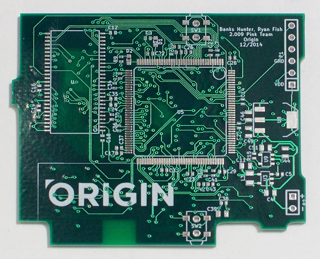
    <figcaption>The unpopulated PCB with beautiful product branding that no one will see. (Except you, dear reader)</figcaption>
  
</figure>

<p>But hang on, we haven’t talked at all about the product design process!  And what an exciting and challenging process it is.</p>

<figure>
  <img src="/images/2.009/portable-mechanical-cooler.jpg" alt="Portable Mechanical Cooler Concept Drawing" width="50%" />
  
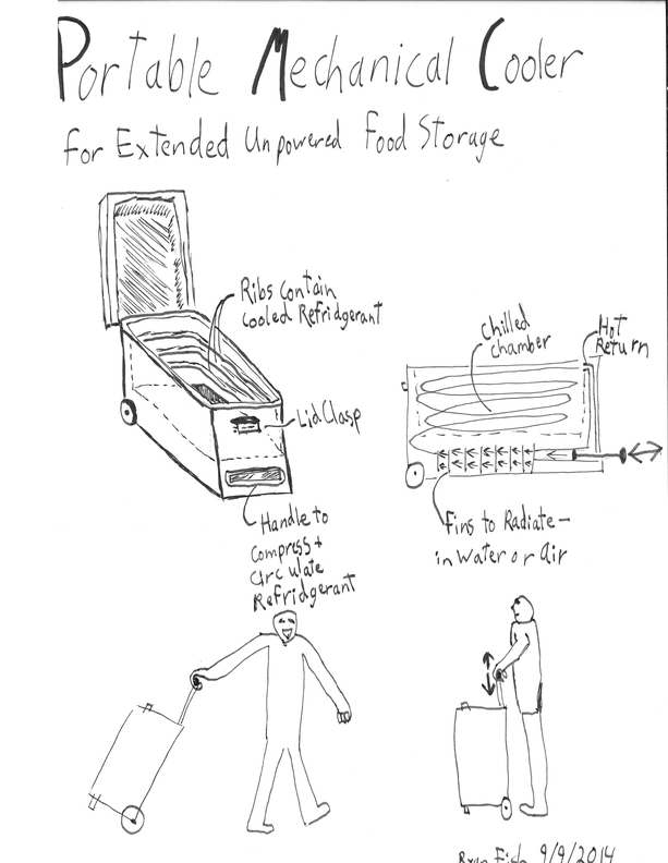
    <figcaption>Portable Mechanical Cooler Concept Drawing</figcaption>
  
</figure>

<p>The ideation process taught in 2.009 is Professor Wallace’s preferred method, and is the same as the one taught in <a href="/projects/2013/05/12/2.00b-is-the-best-freshman-course-ever.html">2.00b</a>.  Essentially, the first round of the process is to gather a many ideas as possible, without filter, to amass a huge board of thought-provoking and not-provoking ideas.  Participants should be encouraged to generate derivatives and spin-offs, along with fresh material.  From there, a brief grouping process can show connections between ideas, and optionally filter ones that were off topic.  With some clearer categories, a more focused brainstorming session can generate new concepts, flesh out old ones, or remix a couple.  At this point, attention should be paid to the core concept of an idea; what problem is it trying to solve?  The first implementation that comes out on paper may not be the best.</p>

<p>From here, we took a fairly democratic path by voting on concepts that seemed interesting and tractable to test, and finally developed a <a href="http://en.wikipedia.org/wiki/Decision_matrix">Pugh Chart</a> to try and select three concepts impartially for initial testing.  The cooler here was one of my concepts that reached the initial stages of testing (and we continued pursuing it until the final vote).  Some other popular ideas we worked on were actively regulated thermalwear, an ice depth testing device, and a portable light-based sports field line marking system.  After several stages of testing, mixing in new ideas and performing more tests with old ones, Pink team reached a point where we had three strong, tested, and exciting ideas.  A pivotal moment for every team in 2.009 is the meeting where the final product is decided.  Luckily, Pink team was full of intelligent, impartial, critical thinkers, and the decision making process went smoothly (and relatively quietly!).</p>

<p>What I said about the first implementation not being the best?  It’s probably true quite frequently, and it was certainly true for our final product, Origin.  Originally (hah!  get it?), another team member and I came up with fairly similar concepts for a wrist-mounted proximity beacon to alert sky divers of others around them, in hopes of preventing <a href="http://skydivemode.com/wp-content/uploads/collision1.jpg">canopy collisions (the #1 cause of death in skydiving)</a>.  Initially, people were concerned about the market size and utility of such a device.  At some point, someone considered the broader need; location information for social/safety/datametrics reasons in areas outside the range or use cases of cell phones.  That was the moment of birth of the idea that grew into <a href="/projects/2015/03/03/2.009-product-engineering-process-(part-iii).html">Origin, our final product</a>.</p>]]></content><author><name>Ryan Fish</name></author><category term="projects" /><summary type="html"><![CDATA[If you just got here and want to know more about the background of course 2.009 at MIT, check out this post part I!]]></summary><media:thumbnail xmlns:media="http://search.yahoo.com/mrss/" url="https://ryan.fish/images/post_thumbs/2_009-part-ii.jpg" /><media:content medium="image" url="https://ryan.fish/images/post_thumbs/2_009-part-ii.jpg" xmlns:media="http://search.yahoo.com/mrss/" /></entry><entry><title type="html">2.009 - Product Engineering Process (Part I)</title><link href="https://ryan.fish/projects/2015/03/02/2.009-product-engineering-process-(part-i).html" rel="alternate" type="text/html" title="2.009 - Product Engineering Process (Part I)" /><published>2015-03-02T15:17:22-05:00</published><updated>2015-03-02T15:17:22-05:00</updated><id>https://ryan.fish/projects/2015/03/02/2.009---product-engineering-process-(part-i)</id><content type="html" xml:base="https://ryan.fish/projects/2015/03/02/2.009-product-engineering-process-(part-i).html"><![CDATA[<h2 id="first-the-hook">First, the hook.</h2>
<figure>
  <img src="/images/2.009/origin-on-slope.jpg" alt="Origin Wristband - Pink Team 2.009" />
  
    <figcaption>Photocredit to Victor Hung</figcaption>
  
</figure>

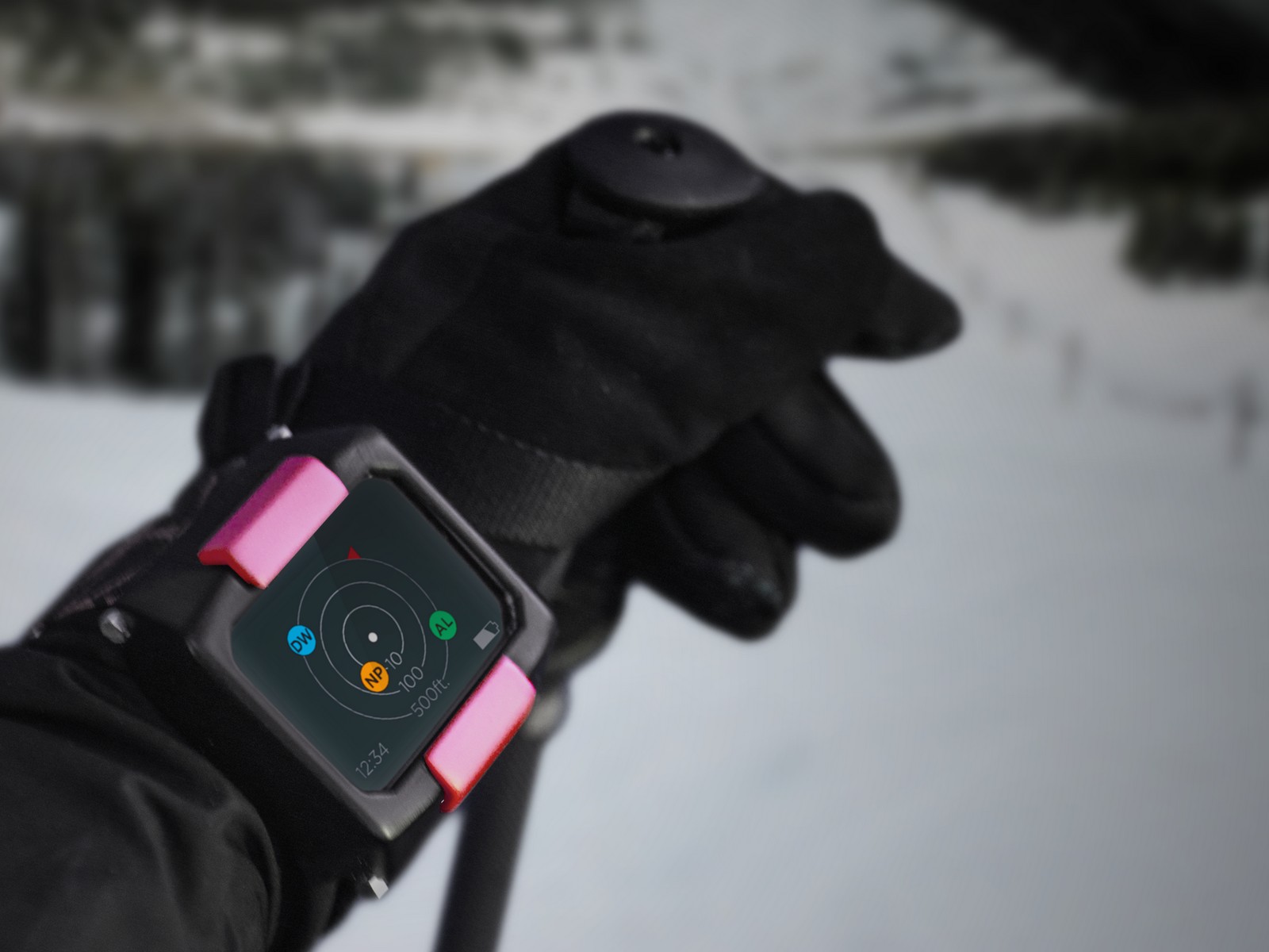
<p>Hopefully now you are wondering, “What is that?”, “Where can I buy one?”, “How did you guys get to test the next [tech company] wearable?”.  Tuck yourself in, and I’ll tell you the story of 2.009</p>

<p>One of MIT’s best known courses, 2.009 takes over 150 MechE seniors through the beginning stages of product design, up to the point of presenting a (hopefully!) functioning prototype product to a live and streamed audience of a couple thousand.  So highly esteemed is the course on campus, within 2 hours of the RSVP system going live, every available seat in Kresge Auditorium (1,200 according to the campus activities site) was claimed.  There’s one reason for the hype, and I can tell you that us students deserve no credit in the class culminating in this incredible final event.</p>

<figure>
  <img src="/images/2.009/gokart-deconstruction-lowres.jpg" alt="2.009 Pink Team dismantles electric go-kart" />
  
    <figcaption>Go-Kart Deconstruction</figcaption>
  
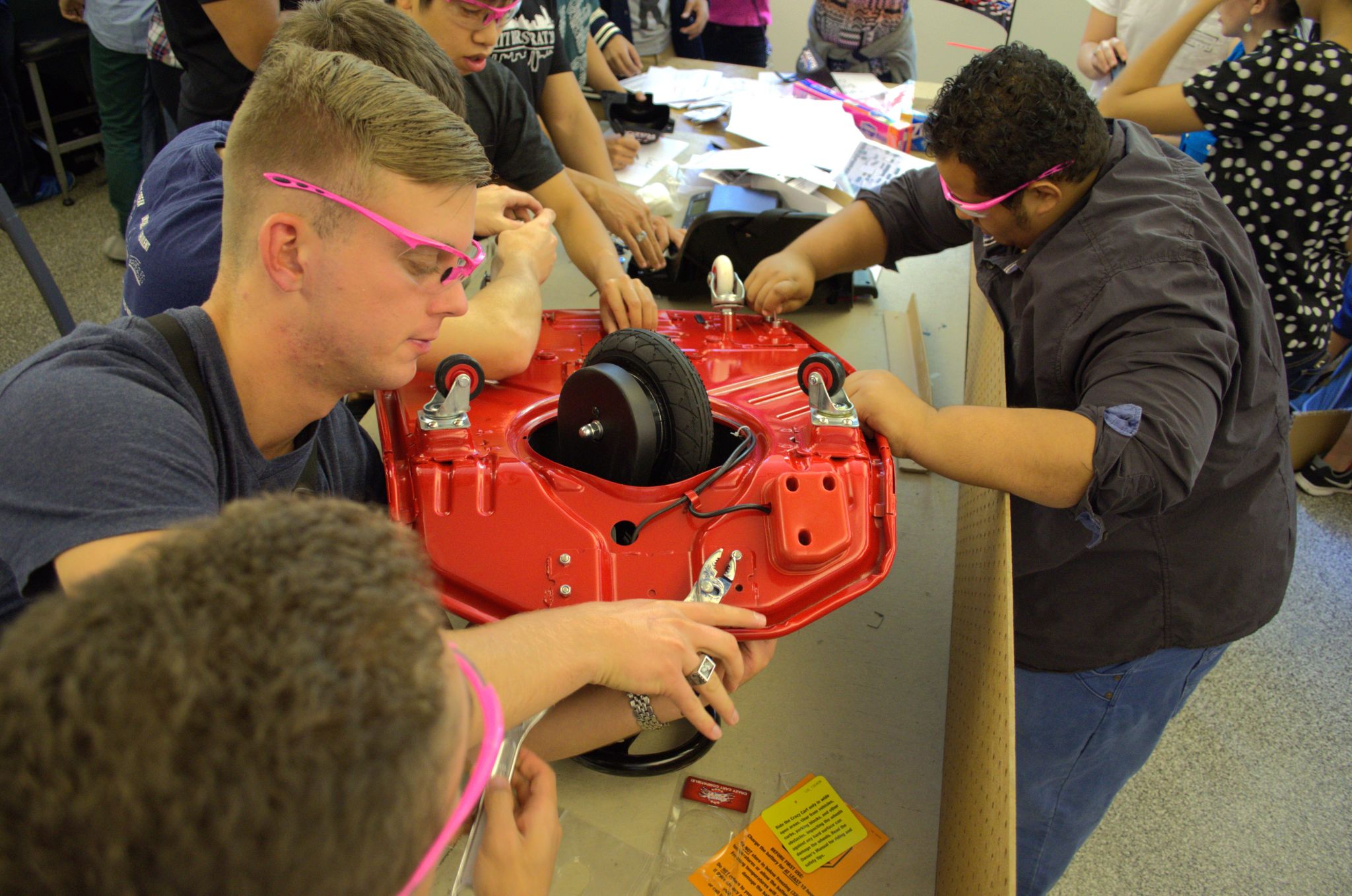
</figure>

<p>The course is taught by Prof. David Wallace, who pours his heart and soul into making the class an unrelenting experience.  As soon as the class is sectioned into 8 teams of 24 (yes, there were 24 people in a team), we start doing team bonding tasks that are cleverly disguised as learning activities.  One of our first tasks as Pink Team was dismantling a product and determining the materials used, how it was assembled, and trying to determine the materials cost of the product.  These activities were way more enjoyable than your typical name-game group activities, and really began to shape the team dynamic.  We learned early on who was loud, who to trust, who had good ideas, etc.</p>

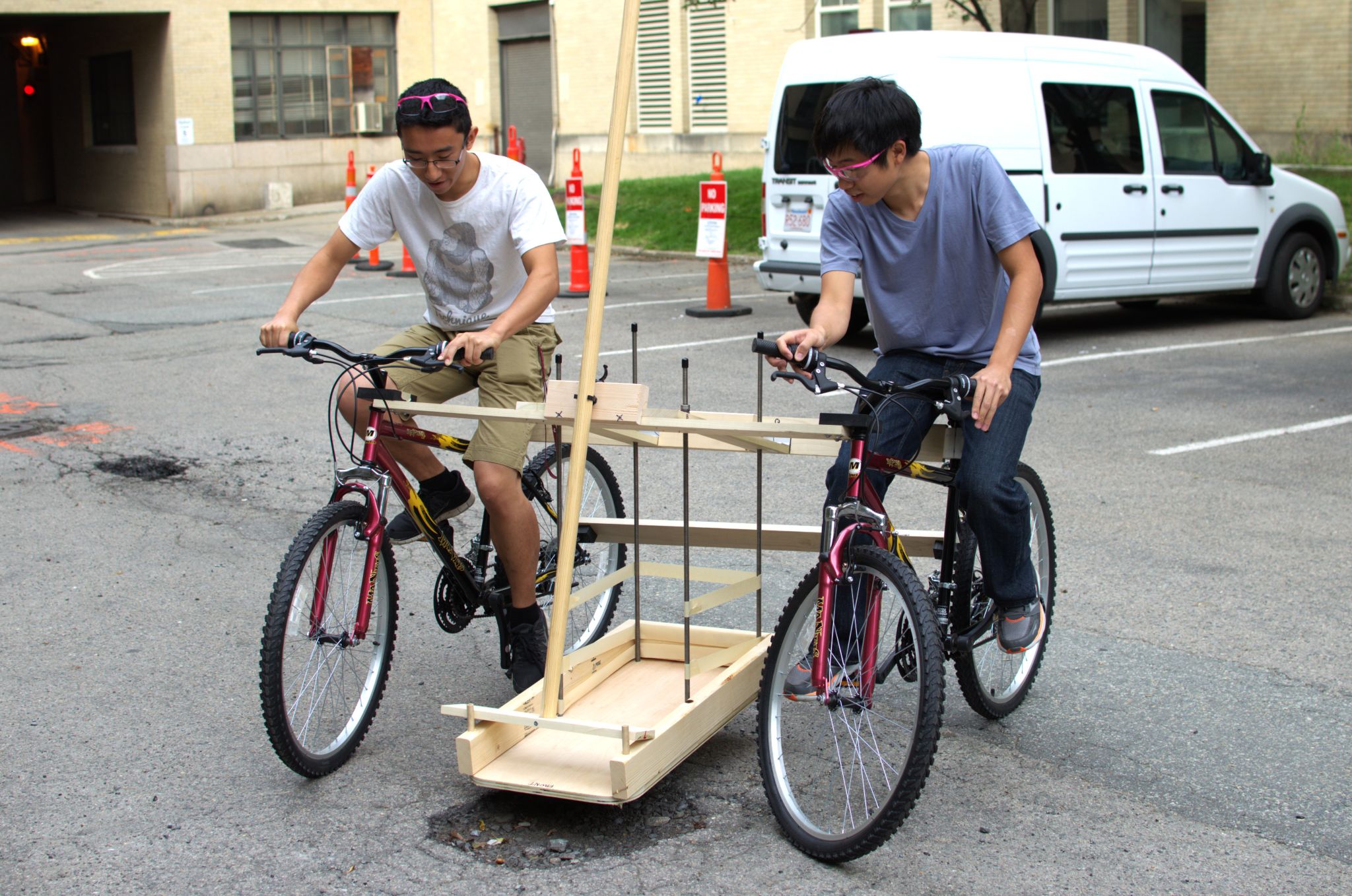
<p>Later we worked on assembling a strange contraption manufactured by the shop staff. An earlier lecture, we had been asked to sketch out an idea for a multi-person vehicle that could load and carry cargo without the operators touching the cargo or the ground.  I had sketched out what was essentially two bikes, side by side, with a bucket in the middle, and a scoop to pile cargo in.  The shop staff apparent found this idea entertaining, so they built it, with some modifications as you can see.  Our team assembled it, then a couple of us took it for a test drive.  We knew this wasn’t the last we would see of it.</p>

<figure>
  <img src="/images/2.009/bike-build-challenge-lowres.jpg" alt="2.009 Pink Team Bike Build Challenge" />
  
    <figcaption>Bike Build Challenge</figcaption>
  
</figure>

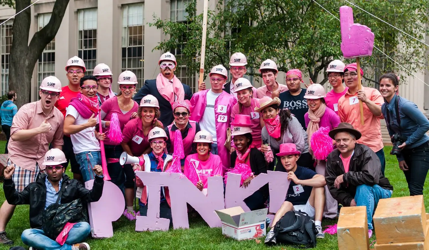
<p>It certainly wasn’t.  The next week, each team took their mobile, stuff-getting, people-transporting device out to Killian Court, the home of the iconic Dome.  Today, however, it was home to tiny volcanoes, stacks of blocks, and hidden treasure!  The teams were given a crate of pom poms and some other paraphernalia with which to cheer on their team as pairs went out to uncover their treasure and bring home the gold.  We had been told ahead of time that there would be a prize for first, but also a prize for spirit.  Knowing that our dual-bike thingy “hobbled” at best, as a team we decided to strike out for the team spirit prize.  We started preparing for the event hours before!  I pulled together some cruft foam insulation to make giant Pink letters, found some surplus scrap wood from Next Big Thing, and took along some rope.  Another division went to a nearby fabric store to get a couple yards of pink cloth.  We ended up building a 20-foot, guy-line supported Pink flag, which we proudly displayed during the competition.  It was a huge team bonding moment because, although we came in dead last getting the treasure, we had a ton of fun being the loudest and proudest out there.  It was a good moment, and I knew every member of the team was in it for the right reasons.</p>

<figure>
  <img src="/images/2.009/pink-pride.jpg" alt="2.009 Pink Team" />
  
    <figcaption>Pink Team Pride! Photocredit to Landon Carter</figcaption>
  
</figure>

<p>Enough about team bonding, and on to <a href="/projects/2015/03/03/2.009-product-engineering-process-(part-ii).html">the technical stuff</a>!</p>]]></content><author><name>Ryan Fish</name></author><category term="projects" /><summary type="html"><![CDATA[First, the hook. Photocredit to Victor Hung]]></summary><media:thumbnail xmlns:media="http://search.yahoo.com/mrss/" url="https://ryan.fish/images/post_thumbs/2_009-part-i.jpg" /><media:content medium="image" url="https://ryan.fish/images/post_thumbs/2_009-part-i.jpg" xmlns:media="http://search.yahoo.com/mrss/" /></entry><entry><title type="html">NASA JPL - Human Interfaces</title><link href="https://ryan.fish/projects/2014/09/19/nasa-jpl-human-interfaces.html" rel="alternate" type="text/html" title="NASA JPL - Human Interfaces" /><published>2014-09-19T07:45:46-04:00</published><updated>2014-09-19T07:45:46-04:00</updated><id>https://ryan.fish/projects/2014/09/19/nasa-jpl---human-interfaces</id><content type="html" xml:base="https://ryan.fish/projects/2014/09/19/nasa-jpl-human-interfaces.html"><![CDATA[<p>My summer internship was a research position on the Human-Robot System team at NASA’s Jet Propulsion Lab (JPL).  Though I am still waiting for some of my work to make it through ITAR checks, here is a video the team made to give an overview of the project!</p>

<iframe width="560" height="315" src="https://www.youtube.com/embed/Iu1mE2LpGaY?si=B-qBgADTR_OgFU0C" title="YouTube video player" frameborder="0" allow="accelerometer; autoplay; clipboard-write; encrypted-media; gyroscope; picture-in-picture; web-share" referrerpolicy="strict-origin-when-cross-origin" allowfullscreen=""></iframe>]]></content><author><name>Ryan Fish</name></author><category term="projects" /><summary type="html"><![CDATA[My summer internship was a research position on the Human-Robot System team at NASA’s Jet Propulsion Lab (JPL). Though I am still waiting for some of my work to make it through ITAR checks, here is a video the team made to give an overview of the project!]]></summary><media:thumbnail xmlns:media="http://search.yahoo.com/mrss/" url="https://ryan.fish/images/post_thumbs/jpl.jpg" /><media:content medium="image" url="https://ryan.fish/images/post_thumbs/jpl.jpg" xmlns:media="http://search.yahoo.com/mrss/" /></entry></feed>